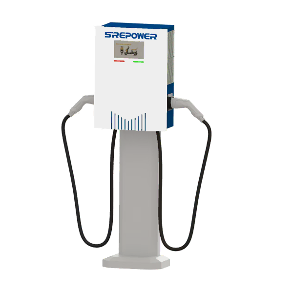
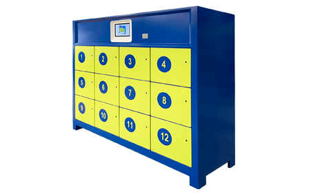
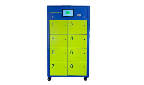
Bidirectional DC 2/3 wheel electric charging station.
The SREPOWE bidirectional DC electric vehicle charging station mainly consists of a human-machine interactive touch screen, card reader, energy metering module, charging module, communication module, charging interface, control module, and station body. The charging station has multiple protection functions, with dual safety protection measures for input and output. It can monitor the connection status of the charging cable in real time during charging, and immediately terminate charging in case of abnormal connection, ensuring personal and vehicle safety during the charging process. Humanized interface display and control guidance function, allowing customers to easily complete the charging process; Provide multiple communication interfaces such as Ethernet and GPRS to the outside world, communicate in real-time with the monitoring center and operation management center, and monitor the charging status in real time.

The purpose of the present invention is to provide a safe, reliable, and orderly charging and discharging control method for bidirectional intelligent charging piles for electric vehicles.
The charging and discharging control method of the bidirectional intelligent charging pile for electric vehicles of the present invention includes the following steps:
(1) Establish a gateway control cabinet between multiple centralized charging stations, and have the grid real-time detection unit in the gateway control cabinet detect the grid operating environment in real time. According to the requirements of "Electric Energy Quality - Harmonics of Public Grid" GB/T 14549-93 and "Electric Energy Quality - Supply Voltage Deviation" GB/T 12325-2008 for 380V public grid, determine whether the grid operating environment is suitable for electric vehicle access. If the grid operating environment meets the requirements, the charging stations will operate normally. Otherwise, compensation will be made through the local compensation device in the gateway control cabinet, and the grid operating environment will be continuously monitored;
(2) Under normal operation of the charging station, after connecting the charging gun to the vehicle charging socket, the user completes IC card authentication on the charging station. The card reader of the charging station obtains user information, and the BMS battery management system on the charging station obtains information about the vehicle battery. The user information and vehicle battery information are transmitted to the charging/discharging control unit of the charging station and displayed on the touch screen;
(3) Each electric vehicle is equipped with an IC card, which corresponds to the license plate number of the electric vehicle. After swiping the card, the owner's identity information, license plate number information, stored value information, and traffic violation records of the electric vehicle can be displayed on the touch screen. The charge/discharge control unit receives the above information on the IC card, detects whether the owner has any traffic violation records, and if so, sends a signal to the touch screen to display the end of service; If not, prompt the user to select functions between the charging module and the discharging module;
(4) If the user selects the charging module, charge according to the charging control method;
(5) If the user selects the discharge module, discharge according to the discharge control method and obtain profits;
(6) The card reader receives user update information from the charge/discharge control unit, writes the update information into the IC card, and prints the bill;
(7) Prompt the user to end swiping the card.
Furthermore, the gateway control cabinet of the present invention is composed of a microprocessor, a real-time detection unit for the power grid, a local compensation device, and a human-machine interaction interface. The microprocessor communicates bidirectionally with the power grid dispatch center to receive charging and discharging instructions, as well as charging time of use electricity price and discharging electricity price information issued by the power grid dispatch center, and to achieve the management of multiple centralized charging piles by the power grid dispatch center; The microprocessor communicates bidirectionally with the real-time detection unit of the power grid to detect the operating environment of the power grid in real time and determine whether the operating environment of the power grid meets the requirements of the 380kV public power grid; The microprocessor communicates bidirectionally with the charging/discharging control unit of the charging station. If the operating environment of the power grid meets the requirements, the charging station operates normally and receives charging and discharging instructions and electricity price information sent by the microprocessor, and the working status of each charging station is fed back to the microprocessor; The microprocessor communicates bidirectionally with the local compensation device. If the operating environment of the power grid does not meet the requirements, a start command is issued to the local compensation device to compensate for reactive power and control harmonics; The microprocessor communicates bidirectionally with the human-machine interface to display charging time of use electricity price and discharging electricity price information, as well as the working status of each charging station for users and management personnel to view.
The charging pile described in the present invention is composed of a charging/discharging control unit, a BMS battery management system, a coin recognition unit, a card reader, a serial keyboard, a touch screen, a metering energy meter, a printer, a bidirectional converter, a voltage/current signal sampling and conditioning circuit, and a driving circuit. The charging/discharging control unit communicates bidirectionally with the microprocessor of the gateway control cabinet for centralized management of multiple charging piles; The charging/discharging control unit communicates bidirectionally with the BMS battery management system to detect information about the vehicle battery; The charge/discharge control unit communicates bidirectionally with the touch screen to receive user settings information and provide feedback on user updates to the touch screen; The charge/discharge control unit is bidirectionally connected to the card reader, used to receive information from the user's IC card and write updated user information into the IC card; The charge/discharge control unit communicates unidirectionally with the voltage and current signal sampling and conditioning circuit to receive voltage and current signals; The charge/discharge control unit outputs signals to the driving circuit through the PWM port, and the driving circuit provides driving signals for the bidirectional inverter; The charge/discharge control unit communicates unidirectionally with the metering energy meter to receive charge/discharge metering signals; The charging/discharging control unit communicates unidirectionally with the coin recognition unit to receive user charging amount information; The charge/discharge control unit communicates unidirectionally with the serial keyboard to receive information set by the user through the keyboard.
The gateway control cabinet of the present invention receives time of use electricity price information and discharge electricity price information formulated by the power grid dispatch center, and displays them on the touch screen of the gateway control cabinet for users and management personnel to view; Also send the electricity price information to the charging/discharging control unit of the charging station for completing the subsequent steps.
The charging control method of the charging module described in the present invention includes the following steps:
(1) The user selects the charging module, enters the charging initialization, detects the vehicle battery's low battery level through the BMS battery management system on the charging station, and displays it on the touch screen of the charging station;
(2) Choose payment method: card payment or cash payment. If you choose card payment, swipe your card in the card slot of the charging station, enter the amount and confirm. If you choose cash payment, add coins at the charging station and confirm the payment amount. Enter the coin recognition system for recognition and confirmation;
(3) Choose charging method: immediate charging, recommended charging, or scheduled charging; If you choose to charge immediately, the charging station will immediately charge at the current charging price; If you choose recommended charging, select this option to connect the electric vehicle to the grid. When the gateway control cabinet detects the low load period of the grid and the power quality of the grid meets the requirements, the charging station calculates the charging amount based on the user set amount and real-time electricity price to charge the electric vehicle. If you choose scheduled charging, you first need to enter the scheduled time, connect the electric vehicle to the grid, and finally calculate the charging amount based on the electricity price information of the scheduled time period. Charging will be executed when the scheduled time arrives;
(4) After the selection is completed, the charging/discharging control unit of the charging station calculates the given charging amount based on the given amount and time of use electricity price information;
(5) The charging/discharging control unit of the charging station compares the given charging amount with the vehicle battery's deficit amount. If the given charging amount is ≤ the vehicle battery's deficit amount, the charging/discharging control unit sends a power on signal to the DC contactor in the charging/discharging circuit, closes the DC contactor, starts charging, and enters the charging process. During the charging process, the charging amount is measured by a metering energy meter connected in series between the vehicle battery and the power grid. The charging/discharging control unit sends the charging information to the touch screen for real-time display of the charging amount. When the charging/discharging control unit detects that the actual charging amount is equal to the given charging amount, the charging/discharging control unit sends a power-off signal to the DC contactor in the charging/discharging circuit, opens the DC contactor, and the charging is completed; If the given charging amount is greater than or equal to the vehicle battery's power loss, the charging/discharging control unit calculates the excess given amount and converts it into the remaining amount based on the current electricity price, enters it into the user's updated information, and then sends an electrical signal to the DC contactor in the charging/discharging circuit by the charging/discharging control unit. The DC contactor closes and charges, and the BMS battery management system continuously detects the battery's power information. When the battery charging status displays 100%, the charging/discharging control unit sends a power-off signal to the DC contactor in the charging/discharging circuit, and the DC contactor opens, completing the charging process;
(6) The charging/discharging control unit of the charging station sends the charging information and remaining amount to the touch screen, which displays the charging information and remaining amount. The charging process ends.
The discharge control method of the discharge module described in the present invention includes the following steps:
(1) The user selects the discharge module, enters the discharge initialization, and detects the current battery information through the BMS battery management system of the charging station. The user sets the cut-off discharge battery charge based on the current battery information;
(2) The real-time detection unit of the gateway control cabinet detects the operating environment of the charging pile in the power grid. During peak load periods, the microprocessor of the gateway control cabinet receives discharge instructions from the power grid dispatch center and sends them to the charging/discharging control unit of the charging pile;
(3) The charging/discharging control unit of the charging station compares the cut-off discharge battery charge with the current battery charge. If the cut-off discharge battery charge is ≥ the current battery charge, the charging/discharging control unit of the charging station displays on the touch screen that the cut-off discharge battery charge is ≥ the current battery charge and prompts the user to end the discharge; If the cut-off discharge battery charge is ≤ the current battery charge, the charge/discharge control unit sends a power signal to the DC contactor in the charge/discharge circuit, closes the DC contactor, discharges, and measures the discharge amount through a metering meter connected in series between the electric vehicle and the grid. The charge/discharge control unit sends the charging information to the touch screen for real-time display of the discharge amount, and the BMS battery management system detects the vehicle battery charge in real time, and the touch screen displays the vehicle battery charge in real time. When the battery charge reaches the user set value, the discharge is completed;
(4) The touch screen displays discharge information, and the charge/discharge control unit calculates and displays user revenue based on the discharge price sent by the gateway control cabinet. The revenue information and discharge power are then sent to the touch screen for display, and the discharge process ends.
Palabras clave calientes:
battery switching station
Fast Swap Cabinet Manufacturer


 WhatsApp Contact